FTTB Optical Signal to RF Output Indoor Fiber Optic Receiver
Model Number: SRB-200
Brand: Softel
MOQ: 1
 With Optical AGC Function
45~1000MHz full coverage
2 RF output ports
01
Product Description
Introduction
SRB series optical receiver is a practical indoor type optical receiver designed to meet the network fiber renovation project. This product has 1 to 2 RF output ports. And set the optical AGC function when +2dBm ~ -6dBm when receiving the output can be maintained at 106dBµV above (dual); shell using cast aluminum shell.
Functional Features
- 45MHz to 1000MHz platform broadband and 1310, 1550 dual window design platform;
- Perfect surge suppression circuit with high-pass filter, with strong resistance to lightning strikes and prevention of surge impact;
- low power consumption design, the whole power consumption is less than 15W; and has a digital display and online operation function.
- Type II transponders can be used;
| Serial No. | Item | Technical parameters | Remarks |
| 1 | Received wavelength | 1290-1600nm | |
| 2 | Input optical reflection loss | >45dB | |
| 3 | Current responsiveness | 0.85A/W(1310nm representative value ) | |
| 4 | Range of received optical power | +3dBm~-9dBm | |
| 5 | output level | 106dBμV±1dB | +2dBm- -6dBm receive |
| 6 | Fiber Type | single mode(9/125nm) | |
| 7 | Fiber Optic Connector Type | FC/APC or SC/APC | |
| 8 | Equivalent noise input current | ≦8PA√Hz | SJ/T10663-1995 NO.4.21 |
| 9 | Frequency bandwidths | 87-1002MHz | |
| 10 | RF in-band flatness | ±±1dB | |
| 11 | RF reflection loss | ≥16dB (45-1000MHz) | |
| 12 | System link metrics | C/N ≥46dB | note |
| C/CTB ≥ 62dB | |||
| C/CSO ≥ 62dB | |||
| 13 | Test Port Level | -20dB | Relative to main output |
| 14 | Gain Adjustment Ranges | 0~20dB(1 dB progress) | (of products) leave the factory 0dB |
| 15 | Range of tilt adjustments | 0~14dB(1 dB progress) | (of products) leave the factory 0dB |
| 16 | RF output connection | F-connector | |
| 17 | Power supply voltage for AC | DC+12A/1A | |
| 18 | maximum power dissipation | ≤10W | |
| Note: Under the specified link loss conditions, configure 59 PAL-D analog TV channel signals within the 550MHz frequency range, and transmit digital modulation signals within the 550 MHz to 862MHz frequency range. The level of the digital modulation signal (within an 8 MHz bandwidth) is 10dB lower than the carrier level of the analog signal. When the optical receiver input optical power is-6 dBm, measure C/CTB, C/CSO, and C/N. The nominal RF output level is at the 862 MHz frequency point, with the actual output being 10dB lower. | |||

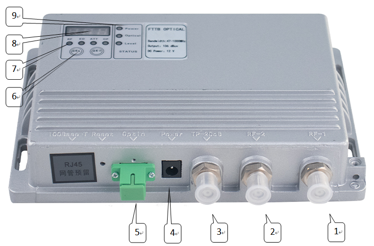
| Serial No. | Name | Functional Description |
| 1 | RF Output1 | RF output port 1 |
| 2 | RF Output2 | RF output port 2 |
| 3 | RF Test site | -20dB RF test port |
| 4 | Power Interface | External power adapter DC output DC12V 1A |
| 5 | Fiber optic interface | FC/APC or SC/APC |
| 6 | Operation key | SELSelect Project SETparameter setting |
| 7 | Indicator lightDigital DisplayStatus light | RF is the output power EQ is the equalization value ATT is the attenuation value OP is the received optical power |
| 8 | Digital Display | RF: display the current total power, unit dBuV too high HI too low LO (factory default 50 sets of programs)
EQ: display the equalization value, unit dB, adjustable range 0-15 ATT: display attenuation value, unit dB, adjustable range 0-15 OP: display the received optical power value, unit dBm too high display HI, too low -9 display LO |
| 9 | Status light | Power: Power indicator, normal for redOptical: Receive optical power indicator, green (+3 to -9) red for the alarm
Level: RF output status indicator, normal green, output is too low or too high display for red |
FTTB Optical Signal to RF Output Indoor Fiber Optic Receiver.pdf