
1. Classification of Fiber Amplifiers
There are three main types of optical amplifiers:
(1) Semiconductor Optical Amplifier (SOA, Semiconductor Optical Amplifier);
(2) Optical fiber amplifiers doped with rare earth elements (erbium Er, thulium Tm, praseodymium Pr, rubidium Nd, etc.), mainly erbium-doped fiber amplifiers (EDFA), as well as thulium-doped fiber amplifiers (TDFA) and praseodymium-doped fiber amplifiers (PDFA), etc.
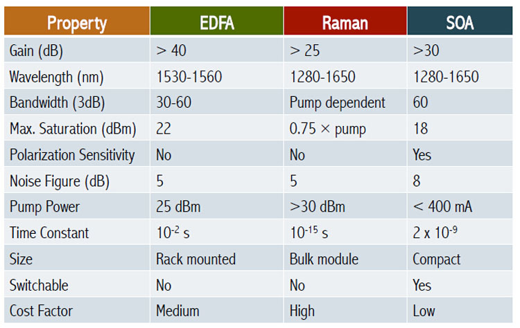
(3) Nonlinear fiber amplifiers, mainly fiber Raman amplifiers (FRA, Fiber Raman Amplifier). The main performance comparison of these optical amplifiers is shown in the table
EDFA (Erbium Doped Fiber Amplifier)
A multi-level laser system can be formed by doping the quartz fiber with rare earth elements (such as Nd, Er, Pr, Tm, etc.), and the input signal light is directly amplified under the action of the pump light. After providing appropriate feedback, a fiber laser is formed. The working wavelength of the Nd-doped fiber amplifier is 1060nm and 1330nm, and its development and application are limited due to deviation from the best sink port of fiber optic communication and other reasons. The operating wavelengths of EDFA and PDFA are respectively in the window of the lowest loss (1550nm) and zero dispersion wavelength (1300nm) of optical fiber communication, and TDFA operates in the S-band, which are very suitable for optical fiber communication system applications. Especially EDFA, the most rapid development, has been practical.
The Principle of EDFA
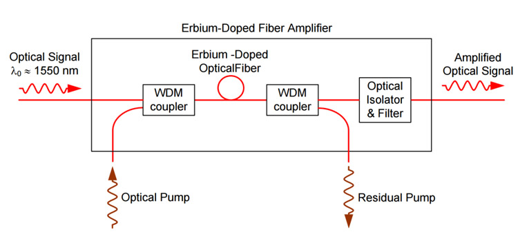
The basic structure of EDFA is shown in Figure 1(a), which is mainly composed of an active medium (erbium-doped silica fiber about tens of meters long, with a core diameter of 3-5 microns and a doping concentration of (25-1000)x10-6) , pump light source (990 or 1480nm LD), optical coupler and optical isolator. Signal light and pump light can propagate in the same direction (codirectional pumping), opposite directions (reverse pumping) or both directions (bidirectional pumping) in the erbium fiber. When the signal light and the pump light are injected into the erbium fiber at the same time, the erbium ions are excited to a high energy level under the action of the pump light (Figure 1 (b), a three-level system), and quickly decay to the metastable energy level , when it returns to the ground state under the action of the incident signal light, it emits photons corresponding to the signal light, so that the signal is amplified. Figure 1 (c) is its amplified spontaneous emission (ASE) spectrum with a large bandwidth (up to 20-40nm) and two peaks corresponding to 1530nm and 1550nm respectively.
The main advantages of EDFA are high gain, large bandwidth, high output power, high pump efficiency, low insertion loss, and insensitivity to polarization state.
2. Problems with Fiber Optical Amplifiers
Although the optical amplifier (especially EDFA) has many outstanding advantages, it is not an ideal amplifier. In addition to the additional noise that reduces the SNR of the signal, there are some other shortcomings, such as:
- Unevenness of the gain spectrum within the amplifier bandwidth affects multi-channel amplification performance;
- When optical amplifiers are cascaded, the effects of ASE noise, fiber dispersion and nonlinear effects will accumulate.
These issues must be considered in application and system design.
3. Application of Optical Amplifier in Optical Fiber Communication System
In the optical fiber communication system, the Fiber Optical Amplifier can be used not only as a power boost amplifier of the transmitter to increase the transmission power, but also as a preamplifier of the receiver to improve the receiving sensitivity, and can also replace the traditional optical-electrical-optical repeater, to extend the transmission distance and realize all-optical communication.
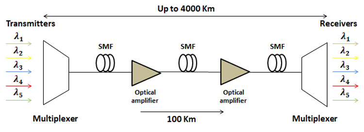
In optical fiber communication systems, the main factors limiting the transmission distance are the loss and dispersion of the optical fiber. Using a narrow-spectrum light source, or working near the zero-dispersion wavelength, the influence of fiber dispersion is small. This system does not need to perform complete signal timing regeneration (3R relay) at each relay station. It is sufficient to directly amplify the optical signal with an optical amplifier (1R relay). Optical amplifiers can be used not only in long-distance trunk systems but also in optical fiber distribution networks, especially in WDM systems, to amplify multiple channels simultaneously.
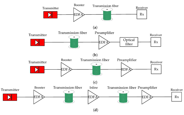
1) Application of Optical Amplifiers in Trunk Optical Fiber Communication Systems
Fig. 2 is a schematic diagram of the application of the optical amplifier in the trunk optical fiber communication system. (a) the picture shows that the optical amplifier is used as the power boost amplifier of the transmitter and the preamplifier of the receiver so that the non-relay distance is doubled. For example, adopting EDFA, the system transmission distance of 1.8Gb/s increases from 120km to 250km or even reaches 400km. Figure 2 (b)-(d) is the application of optical amplifiers in multi-relay systems; Figure (b) is the traditional 3R relay mode; Figure (c) is the mixed relay mode of 3R repeaters and optical amplifiers; Figure 2 (d) It is an all-optical relay mode; in an all-optical communication system, it does not include timing and regeneration circuits, so it is bit-transparent, and there is no “electronic bottle whisker” restriction. As long as the sending and receiving equipment at both ends is replaced, It is easy to upgrade from a low rate to a high rate, and the optical amplifier does not need to be replaced.
2) Application of Optical Amplifier in Optical Fiber Distribution Network
The high power output advantages of optical amplifiers (especially EDFA) are very useful in broadband distribution networks (such as CATV Networks). The traditional CATV network adopts coaxial cable, which needs to be amplified every several hundred meters, and the service radius of the network is about 7km. The optical fiber CATV network using optical amplifiers can not only greatly increase the number of distributed users, but also greatly expand the network path. Recent developments have shown that the distribution of optical fiber/hybrid (HFC) draws the strengths of both and has strong competitiveness.
Figure 4 is an example of an optical fiber distribution network for AM-VSB modulation of 35 channels of TV. The light source of the transmitter is DFB-LD with a wavelength of 1550nm and output power of 3.3dBm. Using 4-level EDFA as a power distribution amplifier, its input power is about -6dBm, and its output power is about 13dBm. Optical receiver sensitivity -9.2d Bm. After 4 levels of distribution, the total number of users has reached 4.2 million, and the network path is more than tens of kilometers. The weighted signal-to-noise ratio of the test was greater than 45dB, and EDFA did not cause a reduction in CSO.
Post time: Apr-23-2023